Difference between revisions of "Lecture 1. - Assignment"
(→The Problem) |
(→The Problem) |
||
| Line 40: | Line 40: | ||
'''The materials:''' | '''The materials:''' | ||
| − | * '''Core:''' ''Steel'' with nonlinear B-H curve ([https://drive.google.com/open?id=1hNmLPbkWXmyxgudRVMNpHXozw-OwUGly Steel1008]); | + | * '''Core/Vasmag:''' ''Steel'' with nonlinear B-H curve ([https://drive.google.com/open?id=1hNmLPbkWXmyxgudRVMNpHXozw-OwUGly Steel1008]); |
| − | * '''Coil:''' ''Copper'' (<math>\mu_r = 1.0</math>) and the ''number of turns'' is 2000. The ''current'' is 0.2 A; | + | * '''Coil/Tekercs:''' ''Copper'' (<math>\mu_r = 1.0</math>) and the ''number of turns'' is 2000. The ''current'' is 0.2 A; |
| − | * '''Region:''' ''Air'' (<math>\mu_r = 1.0</math>). | + | * '''Region/Lezárás:''' ''Air'' (<math>\mu_r = 1.0</math>). |
The task is to determine the inductance of the solenoid valve and the force acting on the iron core. As a first step, it is recommended to validate the simulation with the values given in the table when the iron core is in the middle of the solenoid. Then it is worth examining the two quantities as a function of the position of the iron core. | The task is to determine the inductance of the solenoid valve and the force acting on the iron core. As a first step, it is recommended to validate the simulation with the values given in the table when the iron core is in the middle of the solenoid. Then it is worth examining the two quantities as a function of the position of the iron core. | ||
Revision as of 14:31, 3 April 2021
|
Fuel Injection Solenoid | |
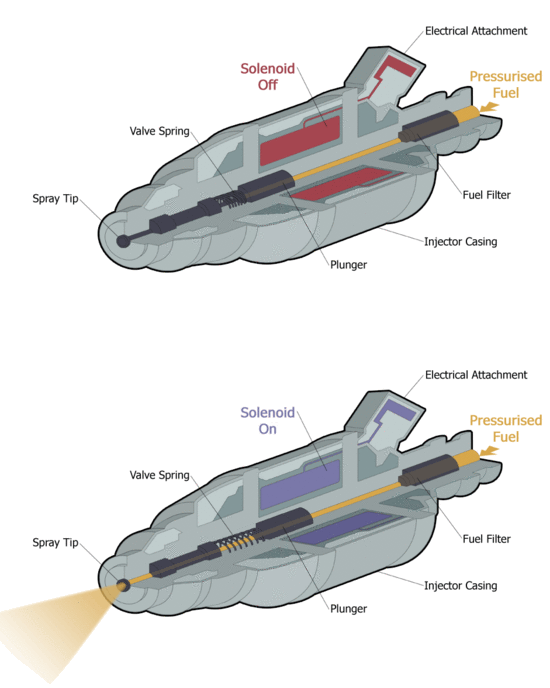
| The fuel injection in operation. [1] | The magnetic flux density vectors in the plunger after switch on the solenoid. |
|
Instructor
|
Teaching Assistants:
|
Contents
Purpose of the Assignment
The student will learn the main steps of the finite element method, such as creating the model (creating or importing geometry), specifying material parameters, boundary conditions, and excitation through simulation of the electromagnetic part of the fuel injector.
Knowledge needed to solve the problem
- The steps of the finite element method;
- Theoretical knowledge of the static magnetic field (for defining materials, for excitation);
- Knowledge of the basics of FEMM and Agros2D.
The Problem
The problem (if we neglect the transient state occurring at the switch on) can be considered as an axisymmetric static magnetic problem. The effect of the movement of the iron core (valve opening/closing) is also examined accordingly, i.e. each position is an individual simulation.
The height of the cylindrical core is 14mm and the radii is 3.6mm. Dimensions of the coil: height is 20mm, inner radii is 4mm and outer radii is 10mm.
The materials:
- Core/Vasmag: Steel with nonlinear B-H curve (Steel1008);
- Coil/Tekercs: Copper ([math]\mu_r = 1.0[/math]) and the number of turns is 2000. The current is 0.2 A;
- Region/Lezárás: Air ([math]\mu_r = 1.0[/math]).
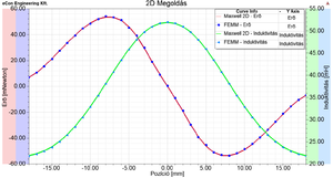
The task is to determine the inductance of the solenoid valve and the force acting on the iron core. As a first step, it is recommended to validate the simulation with the values given in the table when the iron core is in the middle of the solenoid. Then it is worth examining the two quantities as a function of the position of the iron core.
Evaluation of Results
Here you can plot the field quantities (magnetic flux density, magnetic vector potential, etc.) and checked the value of the inductance of the coil and the acting force on the iron core. The following values were obtained for these quantities, the arrangement according to the cross-sectional view being 0 mm position.
The results of the simulation for validation. Software Maxwell 2D Maxwell 3D FEMM Agros2D Inductance [[math]\text{mH}[/math]] 51.911 51.812 51.821 51.89 Force [[math]\mu\text{N}[/math]] 88.603 63.29 74.53 57.45 In addition, it is possible to parameterize the geometry or most of the simulation parameters (position, size, current, number, ...) via script (FEMM - LUA script, Agro2D - Python). The result of a parameterized simulation is shown in the figure where the parameter is the position of the iron core. As a result, the modification of the parameter and the evaluation of results are automatic.
References


