Difference between revisions of "Lecture 2. - Assignment"
(→Az eredmények kiértékelése) |
|||
| Line 9: | Line 9: | ||
[[File:InductionHeating Maxwell3.gif|500px]] | [[File:InductionHeating Maxwell3.gif|500px]] | ||
|- | |- | ||
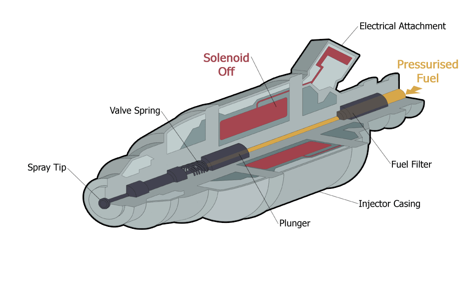
| − | |align=center | Animated cut through diagram of a typical fuel injector <ref>https://upload.wikimedia.org/wikipedia/commons/2/29/Injector3.gif</ref> | + | |align=center | <span style="font-size:88%;">'''Animated cut through diagram of a typical fuel injector.'''</span><ref>https://upload.wikimedia.org/wikipedia/commons/2/29/Injector3.gif</ref> |
| − | |align=center | Animated cut through diagram of a typical fuel injector [Click to see animation]. | + | |align=center | <span style="font-size:88%;">'''Animated cut through diagram of a typical fuel injector'''<span> <span style="font-size:80%;color:blue">[Click to see animation]</span>. |
|- valign=top | |- valign=top | ||
| width=50% | | | width=50% | | ||
Revision as of 09:17, 16 March 2019
|
Induction Heating | |
|
|
|
| Animated cut through diagram of a typical fuel injector.[1] | Animated cut through diagram of a typical fuel injector [Click to see animation]. |
|
Instructor
|
Teaching Assistants:
|


Contents
Purpose of the Assignment
The student will learn the main steps of the finite element method, such as preparing the model (creating or importing geometry), specifying material parameters, boundary conditions and excitation through a time-harmonic simulation. Give a deeper understanding of the physical background of induction heating, melting and hardening.
Knowledge needed to solve the problem
- The steps of the finite element method;
- Theoretical knowledge of time-harmonic field (for defining materials, for excitation).
Steps to solve the problem
After launching ANSYS Electronics Desktop, select Project -> Insert Maxwell 3D Design from the menu.
It is also possible to solve the problem differently from the steps described below. To use ANSYS Maxwell, the Help menu and YouTube videos provide a lot of help.
Creating Geometry
In this case, we work with a pre-prepared geometry. This corresponds to the design of a geometry that a simulator engineer uses for numerical analysis of the device.
So the geometry is imported for this task. The geometry can be imported using the Modeler [math]\to[/math] Import ... menu.
Problem Settings
Defining Materials
In this exercise, the current carrying coil is copper, the iron is cast iron and the surrounding region of the coil and iron is air.
To define the air region, the Region is the simplest way, where
| + X Padding | -X Padding | + Y Padding | -Y Padding | + Z Padding | -Z Padding |
| 0% | 75% | 160% | 160% | 100% | 100% |
Specifying excitation
The excitation must be defined on the surface of the two terminals of the coil. The excitation is 50A, which must be defined on the surface of the coil terminals. When defining it, care must be taken to give the direction of excitation inward on one surface and outward on the other.
Mesh Settings

For the Eddy Current solution, the solver will use adaptive meshing. However, in cases where the eddy current may be significant, it is advisable to use the Skin Depth Based ... mesh operation on the surfaces where it is necessary.
I used this mesh on the surface of the cast iron rod, as shown in the figure. From ANSYS Maxwell 2019R1 version, the adaptive mesh does not change the resolution for those areas where Skin Depth Based ... mesh is defined. The purpose of this is faster convergence, but it is therefore important to define properly the resolution in the penetration depth.
A megoldó beállítása, a szimuláció futtatása
Ahogy a hálózási beállításoknál írtam, adaptívan sűríti a szükséges helyeken a megoldó a felbontást. Azonban az adaptív hálósűrítés paramétereit a megoldónál kell beállítani. Az adaptív lépések maximális száma (Maximum Number of Passes) legyen 10, a hibahatár (Percent Error) pedig 0,5%. A finomítás mértékét adaptív lépésenként (Refinement Per Pass) háromdimenziós feladat esetében célszerű az alapértékről (30%) lejjebb venni. Ez különösen akkor igaz, ha nincs előzetes információnk, hogy milyen módon konvergál, hogyan csökken a hiba a példa esetében. A finomítás mértéke 20% legyen. A megoldónál lehet a gerjesztés frekvenciáját (Adaptive Frequency) megadni, ennél a példánál [math]f = 500~\text{Hz}[/math].
Az előző beállítások mellett még lehetőség van a nemlineáris maradékot (Nonlinear Residual) beállítani, de a példa esetében minden anyag lineár mágnesezési karakterisztikával rendelkezik. Ha szükséges itt lehet a direkt megoldó helyett bekapcsolni az iteratív megoldót, ahol szintén definiálni kell a leállási kritériumként szolgáló hibát (Relative Residual). Az adaptív hálósűrítés mellett, ennél a feladattípusnál lehetőség van magasabb fokú formafüggvények használatára (Use higher order shape functions), illetve ha szükséges a frekvenciasöprés (Frequency Sweep) tartományát és az ahhoz tartozó lépésközt.
Az eredmények kiértékelése
Az 1. lecke példájánál látott változókon (induktivitás, erő) túl meghatározhatjuk a vasdarabban, a tekercsben létrejövő veszteségeket. Ezek a mennyiségek a frekvencia függvényében (Frequency Sweep lehetősége) is vizsgálhatóak.
Az ANSYS Maxwell automatikusan kiszámítja a veszteségeket a feladatban, azonban ha arra vagyunk kíváncsiak, egy-egy térrészben (pl. az öntöttvas rúdban) mekkora az örvényáram okozta veszteség, akkor azt nekünk kell kiszámolni a Calculator (Maxwell 3D [math]\to[/math] Fields [math]\to[/math] Calculator...) segítségével. Az örvényáramú veszteség a következő összefüggéssel számítható
- [math] P_{ö} = \frac{1}{2}\int_{V} \vec{J}\cdot\vec{E}^{*}\,\text{d}V = \int_{V} \frac{\vec{J}\cdot\vec{J}^{*}}{2\sigma}\,\text{d}V\quad[\text{W}][/math].
Azonban a fenti összefüggés helyett a Calculator-ban a következő lépéseket kell elvégezni
- Input [math]\to[/math] Quantity [math]\to[/math] OhmicLoss
- Input [math]\to[/math] Geometry [math]\to[/math] Itt kiválasztjuk a térfogatot, ahol számolni szeretnénk a veszteséget
- Scalar [math]\to[/math] [math]\int[/math] (Integrálás)
- Output [math]\to[/math] Eval
A térváltozók is megjeleníthetőek különböző formában erre mutat egy-egy példát a következő két ábra.
|
|
|
| A tekercs körül kialakuló mágneses térerősség (ANSYS Maxwell). | Az örvényáram veszteség az öntöttvas rúd felületén (ANSYS Maxwell). |


A feladat ANSYS Discovery AIM segítségével is megoldható, ahogy a következő két ábra mutatja.
|
|
|
| A tekercs körül kialakuló mágneses térerősség (ANSYS Discovery AIM). | Az örvényáram veszteség az öntöttvas rúd felületén (ANSYS Discovery AIM). |


References